

How to choose the output capacitor in the flyback circuit

2021/09/03
The output of the switching power supply has capacitors, most of which are electrolytic capacitors. The selection of electrolytic capacitors is generally based on their withstand voltage, ripple current, ripple voltage, etc., but the size of the capacitance value is now mostly based on Experience value to choose, this article will teach you to analyze how to choose the electrolytic capacitor in the DCM mode of the flyback circuit.
At the beginning, you need to know how to select the withstand voltage value of the electrolytic capacitor. In fact, the selection of the voltage of the electrolytic capacitor is very simple. Generally, it is based on the output voltage, and then the overvoltage voltage value must be considered. The withstand voltage value is generally higher than the output voltage. The overvoltage value is 1.2 times higher.
The choice of the capacitance value is mainly based on the value of the ripple voltage. We know that the process of charging and discharging the capacitor will generate a ripple voltage. In addition, the electrolytic capacitor is not an ideal capacitor. It has ESR, ESL, etc. are connected in series on the electrolytic capacitor, and the high-frequency ripple current will generate a ripple voltage. This ripple voltage is not small, so it needs to be considered in the actual calculation.
The life of an electrolytic capacitor is not only related to the temperature of the capacitor, but also has a corresponding impact on the RMS ripple current. Next, the flyback circuit of ICW3783B-12V1A will be explained in detail, as shown in Figure 2.
First, familiarize yourself with the ICW3783B product. ICW3783B is the latest generation of constant voltage and constant current control chip of Hefei Aichuang Microelectronics Technology Co., Ltd. It optimizes the performance of dynamic response and drive, and can achieve greater output power. The chip has a built-in power transistor with Vcво of 850V, which is suitable for chargers and adapters. ICW3783B adopts the unique output line loss compensation technology, which can effectively compensate the loss voltage drop of the output current on the output line. ICW3783B has multiple protection functions, including open circuit protection, over voltage protection, short circuit protection, over temperature protection and other functions. ICW3783B adopts SOP-7 package, its internal block diagram is shown in Figure 1.
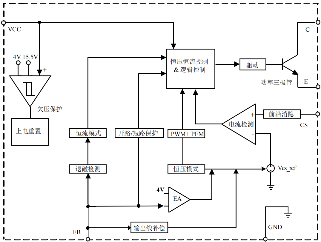
figure 1
According to the application schematic diagram of ICW3783B in Fig. 2, we must first analyze several currents on the electrolytic capacitor. IL is the current after the diode of the subsequent circuit is turned on, Io is the current of the output load, lc is the current on the capacitor, and the capacitor is There are charging current Ic and discharging current -Ic. For a stable power supply, the charging current on the electrolytic capacitor should be equal to the discharging current. If the charging current is greater than the discharging current, the output voltage will definitely increase. If the charging current is less than the discharging current. , the output voltage will drop.
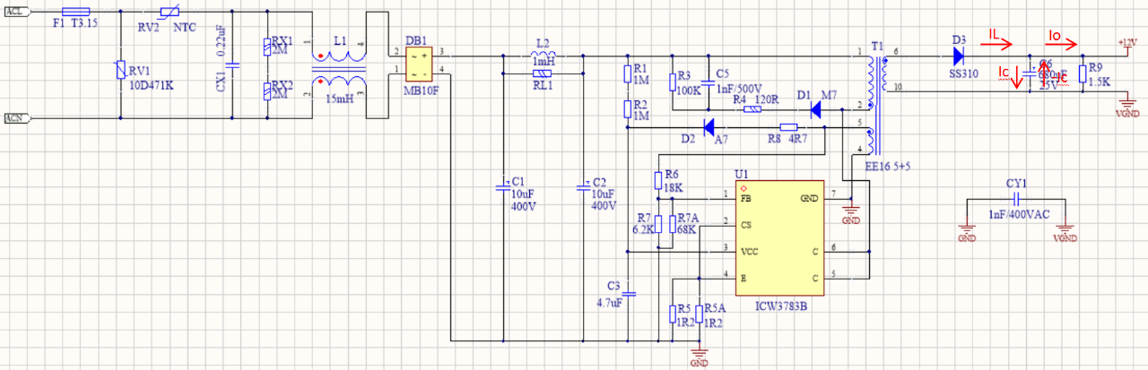
figure 2
Then, looking at the waveform in Figure 3 specifically, Isp in Figure 3 is the maximum current of the secondary side transformer, which is the maximum current Ip of the primary side converted from the turns ratio, Isp=n*lp, n is the primary side and the secondary side. Turns ratio, on is the turn-on period of the primary side, and off is the turn-off period of the primary side.
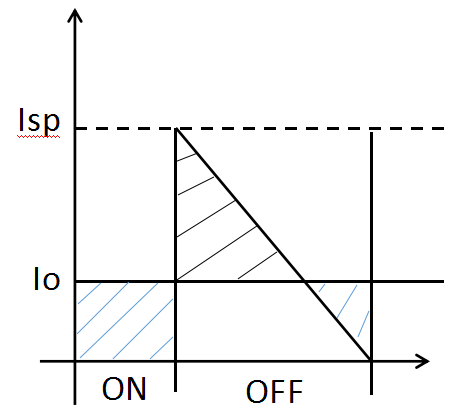
image 3
From the waveform in Figure 3, it can be seen that:
1. When the primary side is turned on, the output current Io is provided by the electrolytic capacitor.
2. When the primary side is turned off, the current conduction value Isp on the winding is greater than the output current Io. At this time, the output current is provided by the current IL after the diode after the transformer is turned on, and the electrolytic capacitor is also being charged.
3. When the current IL after the subsequent diode is turned on is less than the output current Io, part of the output current Io is provided by the current IL after the subsequent diode is turned on, and a part is provided by the discharge current -Ic of the electrolytic capacitor.
The charging and discharging of the capacitor is because the voltage of the capacitor changes. When charging, it generally starts from the low voltage of the capacitor. When the transformer winding current is equal to the output current, the ripple voltage of the capacitor is the maximum value, and then starts to discharge, and discharges until Until the diode is turned on, the capacitor ripple voltage at this time is the lowest.
So, how to calculate the parameters of the ripple current caused by the charging and discharging of the capacitor? In fact, the whole process of charging is the process of the ripple voltage on the capacitor from the lowest to the highest, so as long as the charging time is known, the ripple voltage can be calculated .
First of all, it is necessary to find the time for charging the capacitor, that is, the entire time that the diode current is greater than the output current, then according to the actual inductor voltage formula V=L*di/dt, di=lsp-lo, dt is the diode current greater than the output current. The time period Tc, Tc is calculated according to formula 1.
Tc=L*(lsp-lo)/Vo (Formula 1)
Because the inductor current decreases linearly throughout the charging time, the average current in the entire charging time is Ic, which is calculated as Equation 2.
Ic=(lsp-lo)/2 (Formula 2)
Then according to the charging formula 3 of the capacitor, V is the ripple voltage caused by charging.
C*V=Tc*Ic (Equation 3)
According to the above three formulas, the capacitance value C of the capacitor can be obtained, and C is calculated as formula 4.
C=[Ls*(lsp-lo)^2]/(2Vo*Vrip) (Formula 4)
Finally, the capacitance value calculated by the above formula is a theoretical value. Since most output capacitors use electrolytic capacitors, electrolytic capacitors have ESR, so the actual value is much larger than the calculated value.
In the actual electrolytic capacitor to take the ripple voltage value, it is calculated according to the size of the ESR and the size of the ripple current. The peak current flowing through the capacitor is multiplied by the ESR, which is less than the required ripple voltage. The calculation is as formula 5, and then find a suitable electrolytic capacitor according to the ESR.
Vrip=lsp*ESR (Equation 5)
More News
What is LED driver power supply?
2021-09-15