

What is LED driver power supply?

2021/08/06
LED drive power is an important part that affects the reliability and adaptability of LED light sources. At present, the mains electricity in our country is 220V alternating current, and the LED light source is a semiconductor light source, which is usually powered by a low-voltage DC voltage.
As a new type of lighting source, LED lamps are gradually being applied on a large scale and in a wide range; the core part that determines the performance and life of LED lamps is the LED drive circuit. Stability and output ripple are closely related.
What is LED?
Light-emitting diodes are referred to as LEDs, as shown in Figure 1. Made of compounds containing gallium (Ga), arsenic (As), phosphorus (P), nitrogen (N), and the like.

figure 1
When electrons and holes recombine, they can emit visible light, so they can be used to make light-emitting diodes. Used as indicator lights in circuits and instruments, or composed of text or digital displays. Gallium arsenide diodes emit red light, gallium phosphide diodes emit green light, silicon carbide diodes emit yellow light, and gallium nitride diodes emit blue light. Due to chemical properties, it can be divided into organic light emitting diode OLED and inorganic light emitting diode LED.
The working principle of LED
Like ordinary diodes, light-emitting diodes are composed of a PN junction and also have unidirectional conductivity. When a forward voltage is applied to the light-emitting diode, the holes injected from the P region to the N region and the electrons injected from the N region to the P region will be respectively connected with the electrons in the N region and the empty holes in the P region within a few microns of the PN junction. Hole recombination, resulting in spontaneous emission of fluorescence.
The energy states of electrons and holes in different semiconductor materials are different, mainly because the energy released by electrons and holes when they recombine is different. The more energy released, the shorter the wavelength of light emitted. Commonly used are red, green and yellow diodes. The reverse breakdown voltage of the light-emitting diode is greater than 5 volts. Its forward volt-ampere characteristic curve is very steep, as shown in Figure 2, and a current-limiting resistor must be connected in series to control the current through the diode.
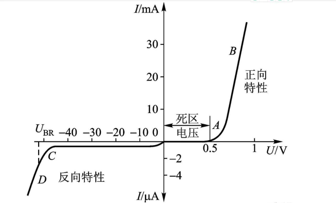
figure 2
The core part of the light-emitting diode is a wafer composed of P-type semiconductors and N-type semiconductors, and there is a transition layer between the P-type semiconductors and the N-type semiconductors, which is called a PN junction. In the PN junction of some semiconductor materials, when the injected minority carriers recombine with the majority carriers, the excess energy is released in the form of light, thereby directly converting electrical energy into light energy.
When the reverse voltage is applied to the PN junction, it is difficult for minority carriers to inject, so it does not emit light. When it is in a forward working state (that is, a forward voltage is applied to both ends), when the current flows from the LED anode to the cathode, the semiconductor crystal emits light of different colors from ultraviolet to infrared, and the intensity of the light is related to the current.
Classification of LED drive power
Constant flow:
1. The output current of the constant current drive circuit is constant, but the output DC voltage varies within a certain range with the load resistance value. The smaller the load resistance value, the lower the output voltage. the higher the voltage;
2. The constant current circuit is not afraid of short circuit of the load, but it is strictly forbidden to open the load completely;
3. It is ideal to drive LED with constant current drive circuit, but the price is relatively high;
4. Pay attention to the maximum withstand current and voltage used, which limits the number of LEDs used.
Regulator:
1. After the parameters in the voltage regulator circuit are determined, the output voltage is fixed, but the output current changes with the increase or decrease of the load;
2. The voltage stabilizing circuit is not afraid of the open circuit of the load, but it is strictly forbidden to short-circuit the load completely;
3. The LED is driven by a voltage-stabilizing drive circuit, and each string of LEDs needs to be added with a suitable resistor to make each string of LEDs display an average brightness;
4. The brightness will be affected by the voltage change from rectification.
This article is mainly about the introduction of LED constant current drive power supply. The following is an example of ICW2170 for analysis.
Introduction of ICW2170 products
ICW2170 is a CMOS step-up DC/DC LED driver composed of reference voltage source, oscillator circuit, error amplifier circuit, phase compensation circuit, current limit circuit, etc. from Hefei Aichuang Microelectronics Technology Co., Ltd.
Due to the built-in enhancement mode N-channel power MOSFET with low on-resistance, it is suitable for application circuits requiring high efficiency and high output current. The output current can be limited by connecting a current sense resistor (RSENSE) to the VSENSE terminal. The constant current size can be set freely: for example, when RSENSE=143mΩ is set, the constant current value is 750mA.
Ceramic capacitors can be used for the output capacitors around the ICW2170. In addition, the SOP8 package is adopted, which has good heat dissipation and can be applied to high-density mounting, high-precision and high-efficiency applications.
The working principle of ICW2170
Figure 3 is a functional schematic diagram of ICW2170. Through the schematic analysis, when the chip starts to be powered on, if the input voltage is low, the chip enters the undervoltage lockout protection state; when the VDD voltage is greater than 2.4V, the chip leaves the undervoltage lockout state and enables the enable control terminal of the chip, and then The chip starts to work normally. There is a soft-start circuit inside the chip, and the time is 2ms. After 2ms, the internal oscillator starts to work.
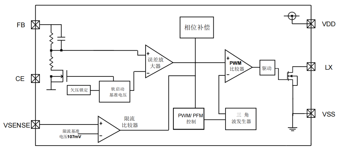
image 3
When the enhancement-mode N-channel power MOSFET is ON, current can be supplied from the input voltage (VIN), and at the same time, energy is accumulated in the inductor. Subsequently, when the enhancement-mode N-channel power MOSFET is turned OFF, the current accumulated in the inductor is discharged, so the voltage of the CONT terminal is boosted, and the current is discharged to the VOUT terminal through the diode. The released current is accumulated until the output capacitor (COUT) becomes a voltage, and the VOUT potential rises until the FB pin voltage reaches the same potential as the internal reference voltage.
Finally, when applying this product, you should pay attention to the following matters when drawing the PCB:
1. When laying out on the PCB, the LX/GND pin of the chip should pay attention to the large area of copper to reduce the thermal resistance and increase the heat dissipation;
2. The input capacitor should be as close to the VIN pin of the chip as possible, and a 0.1uF ceramic capacitor should be placed next to the VIN pin if possible;
3. The voltage of FB is taken from the output capacitor and away from the power area;
4. The EN pin of the chip should be connected to the input end.
More News
What is LED driver power supply?
2021-09-15